Document


pt-filter_082016_eng.pdf


Contenu du document
Dry separator PT-Filter
For highly effective, energy-efficient
dry separation of fine dust in small spaces
The PT Filter series is especially
suitable for the separation of fine,
free-flowing dust created by mechani-
cal and thermal processes.
2
Examples of
applications Mechanical and thermal processes during which dry,
airborne dust is created
Grinding Painting
Drilling, Turning Blasting
Brushing Thermal Joining
Fettling Thermal Cutting
Blending, Weighing Thermal Spraying
The PT filter series is most suitable
for the separation of very fine dusts in
numerous applications. Virtually all
types of dust can be separated
efficiently with these filters. Among
its multiple applications are metals
processing and finishing, as well as
plastics processing, the chemical and pharmaceutical industries, or ceram-
ics, stoneware and earthenware. The
PT-Filter series is especially notewor -
thy in the dry separation of wet paint
overspray. A useful feature is the
filter plate exchange on the clean air
side, which facilitates maintenance
and reduces the overall height. The PT filters have a modular design.
This enables flexibility for different
requirements, such as dust charac-
teristics or the air flow to be extract-
ed, etc. The sturdy and silent units
enable trouble-free 24-hour opera-
tion at a continuous air flow rate.
• Filter elements for a variety of
material properties
• Modular design
• Disassembles into identical
components •
Flexible installation options
• Simplified installation in
hard-to-access area
• Access on the clean air side to the
horizontally installed filter
elements •
Vertically designed upward
pressure relief is possible
• Suitable for explosion protection
measures for indoor and outdoor
installations
The task
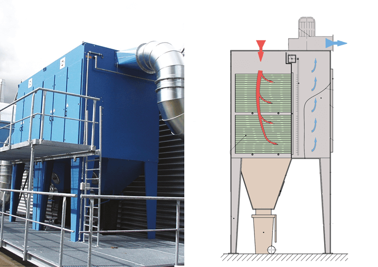
Advantages 1 Clean air outlet (with top-mounted fan)
2 radial fan
3 dirty air inlet
4 compressed air tank
5 electromagnetical diaphragm valves
6 blowing shoes
7 inspection door
8 clean gas room
9 filter elements
10 inspection door
11 hopper
12 dust collection container 220 L
13 substructure
Description
1 3 25 4
6
7
8
9
10
11
12
13
3
The PT series operates according to
the downflow principle. The dust lad-
en air enters via the air inlet into the
upper section of the filter housing
and flows around the filter elements
from top down. The polluted air is
sucked through the filter elements that are fixed to the slotted wall and
the dust collects on the surface of the
filter elements. Cleaning of the filter
elements is achieved by means of
compressed air pulses during filtra-
tion operation. Thus, the air volume
of the fan remains nearly constant. The clean gas (cleaned air) exits
through the top of the unit and in
most cases can be re-circulated into
the work area or is ducted outdoors.
The separated dust falls into the dust
collector section.
Operation
The filter elements are of high quality
and are available in a variety of mate-
rials. Each filter element is selected
depending on the specific application in order to achieve optimum filtration,
separation efficiency, and length of
service.
Filter elements
The pulse cleaning cycle can be ad-
justed for each application by means
of a control unit. The air flow of the
fan remains nearly constant. The cleaning operation is activated either
by a differential pressure regulator
while in operation, or by a program-
mable downtime cleaning cycle.
Cleaning the filter
elements
The air-tight and dust-tight disposal
bins are connected to the filter‘s hop-
per with a clamping device, simplify-
ing the exchange of dust collector
containers.
For larger dust volumes or in 24-hour
operations, the waste disposal is
continuous via rotary valves, into dis-
posal tanks or Big Bags.
Waste disposal
Waste disposal 1
- gate valve
- 220-liter container Waste disposal 2
- rotary lock
- Big-Bag/container
The direct-drive radial fan is very
silent. Depending on the size of the
filter unit, the fan is either integrated, top-mounted or placed next to it.
Fan section
Air recirculation is often possible
with the use of high-quality filter ele-
ments. The cleaned air can be ducted
and channeled (even with heat ex-
changers) to the outdoors, or re-circu-
lated back into the workplace. Alternate
venting or recirculation can be ac-
complished by activating a switch
within the exhaust duct. We will be
pleased to furnish you with detailed
information regarding the feasibility of a recirculation system, ensuring
compliance with your local rules and
regulations.
Venting outdoors
or re-circulation
It is possible to equip PT Filter sys-
tems with security technology if
combustible or explosive dusts are created during the manufacturing
process.
Safety
The PT-FILTERs are specifically con-
figured for indoor installation, prefer -
ably adjacent to the equipment to
be extracted. Outdoor installation is possible with appropriate weather
protection measures and required
sound insulation.
Placement
Technical data
PT-Filter
© Keller Lufttechnik - all rights reserved. Subject to modifications. 07/2021
Type-114 Type-121 Type-228
Type-242
Unit types PT-114PT-121PT-228PT-242
Max. air flow [m³/h] 1600024000 32000 48000
Motor power [kW] 11,0 – 18,518,5 – 30,022,0 – 37,030,0 – 45,0
Max. number of filter elements [pcs.] 14212842
Filter surface area [m²] 129,7194,6259,4389,3
Dimensions (L/W/H) [mm] 2444 x 1680 x 5720 2444 x 2450 x 6320 2444 x 1680 x 68702444 x 2450 x 7470
subject to modification
*) Only one valve is controlled, nominal pressure 6 bar
Cleaning interval Standard PT-114/228 1,5 min
Cleaning interval Standard PT-121/242 1 min
Dry separator PT-Filter
The PT filter with a fluid hopper is made for compact installation indoors.
Entreprise(s) concernée(s) :
Produit(s) concerné(s) :
Date d'upload du document :
lundi 9 janvier 2023