Document


FP-COFFRET-PILOTES-ATEX-CXD


Contenu du document
COFFRET PILOTES
ATEX CXD
MECAIR
PROTECTION
MANUTENTION FILTRATION
PROTECTION I MANUTENTION I FIL
VRAC
wwwpmfil.
2
03
CXD 5 - ..V/..Hz - R
Coil voltage/frequency
Nominal values Operating range
24/50 24 V/50 Hz
24/60 24 V/60 Hz
24/DC 24 V/DC 15W
110/50 110–127 V/50 Hz
110/60 110–127 V/60 Hz
110/DC 110 V / DC
220/50 220–240 V/50 Hz
220/60 220–240 V/60 Hz
Part Number Code:
CXD
Explosion-proof enclosure
Number of solenoid pilots
CXD 1-2-3-4 (small enclosure)
CXD 5-6-7-8 (large enclosure)
Heater element with thermostat
Available in two versions:
GTRM 50 = 70 WATT (for CXD 4)
GTRM 100 = 100 WATT (for CSN 8)
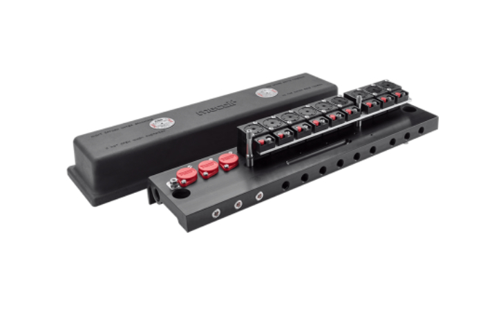
DESCRIPTION
The CXD explosion-proof solenoid
enclosure is designed for those
applications where the atmosphere
may present the possibility of
combustion. The CXD enclosure is
explosion proof with the following grade
of protection: II 2 G Ex d IIB T5 - II 2 D
Ex tD A21 IP67 T100°C. This ensures
that any spark, resulting from the
electrical activation of the solenoid, will
be restricted within the interior of the
enclosure.
The CXD explosion-proof enclosure
is certified in accordance with the
European Directive 94/9/CE (ATEX).
The CXD Series is available in two
models/sizes:
• CXD 4: from 1 to 4 solenoid pilots
• CXD 8: from 5 to 8 solenoid pilots
Each solenoid pilot, energised in
sequence, commands a corresponding
VEM type diaphragm valve, by way of
a 6 mm internal diameter pneumatic
tube being less than 2 metres in length.
The control consists in releasing
the compressed air from the upper
chamber of the valve and its piping.
The CXD enclosure is supplied
complete with fixing brackets. The
common terminal is pre-wired.
The CXD solenoid base is made
of extruded aluminium, while the
cover is in diecast aluminium. Both
are anodised for protection against
aggressive agents. The CXD enclosure
features a common exhaust port,
located on the underside of the unit.
The exhaust is open to the atmosphere
and can be piped or muted with a
silencer. Within the enclosure a safety
device is installed in order to cut off
the power supply to the solenoids
in case of an abnormal increase in
temperature within the enclosure. This
device is recognised as GTRM-1. It is
possible to install within the enclosure
a heat resistor group complete with
thermostat for installation in cold
GENERAL FEATURES
Operating temperature ?20° C/+ 60°C
Weight CXD 4 – 5 kg
CXD 8 – 8.5 kg
CONSTRUCTION FEATURES
Top cover Diecast aluminium (anodised)
Base Extruded aluminium (anodised)
Pilot Stainless steel
Gaskets NBR
ELECTRICAL FEATURES
Coil insulation Class H
Electrical connection 2 × ½ ? NPT for CXD 1–4
2 × ¾ ? NPT for CXD 5–8
Electrical protection II 2 G Ex d IIB T5 - II 2 D Ex tD A21 IP67 T100° C
Voltage and frequency AC: 24/110/220 V 50/60 Hz
DC: 24/110 V
Pneumatic connections To VEM Valves
¼ ? female Gas
Common exhaust,
No. 2 connections
38? female Gas
Approvals – INERIS INERIS 03 ATEX 0069X II 2GD
HOW TO ORDER
climates where low temperature is
a problem. GTRM-2 maintains an
internal temperature of approximately
+ 4°C, and is available in two models:
• GTRM 50, for CXD 4
• GTRM 120, for CXD 8
(PLEASE NOTE: single diaphragm 1½?
VEM valve not suitable with remote pilot.)
MECAIR HAZARDOUS ENCLOSURES
CXD
FILTRATION
3
04
DIMENSIONS (mm)
CXD 4
CXD 8
MECAIR HAZARDOUS ENCLOSURES
CXD
FILTRATION
4
05
SPARE PARTS
CXD 4 – CXD 8
POS. DESCRIPTION CODE
1Pilot group complete with coil KIT ELA2 - ../.. (*)
2 Solenoid coil (*) KIT SA2 - ../.. (*)
3 Ferrule tube complete KIT ECL 28 X
4 Heater for CXD4 KIT GRT 50 - 220 V 50/60 Hz
4 Heater for CXD8 KIT GRT 100 - 220 V 50/60 Hz
5 Circuit – for internal temperature control KIT GTRM - 1
5 Circuit – for internal temperature control and
resistor control KIT GTRM - 2
(*) Specify voltage and frequency (or DC).
RECOMMENDED SPARE PARTS
For start-up:
? 5% of supply (min. 1 piece):
•
p ilot group (1), complete with coil.
For first two years of service:
? 10% of supply (min. 2 pieces):
•
p ilot group (1), complete with coil.
ELECTRICAL CONNECTIONS
ELECTRICAL CONNECTIONS
A Loosen the screws (8) and remove the top cover (9).
B Connect the solenoid coils as described in drawing [E1 if without the heater or
E2 if with heater].
Use a multi-core cable to: 1 wire to pre-wired common terminal (11) and 1 wire
to each solenoid coil.
C Connect the thermostatically controlled heater (optional) as per drawing [E2].
D Refit the top cover (9) ensuring the correct position of the seal (12).
E1 – INTERNAL TEMPERATURE CONTROL E1 – INTERNAL TEMPERATURE CONTROL (GTRM-1)
Common - solenoid coil inlet
Wiring Terminal Thermal Fuse
Wiring Terminal
Common - solenoid coil output
MECAIR HAZARDOUS ENCLOSURES
CXD
FILTRATION
5
06
Pilot Enclosure CXDTank Diaphragm Valve
Pilot Enclosure CXD
Tank
Diaphragm Valve
Certified in accordance with ATEX 94/9/EC
E2 – INTERNAL TEMPERATURE CONTROL AND RESISTOR E2 – INTERNAL TEMPERATURE CONTROL AND THERMOSTAT
(G TRM-2)
Common Solenoid Coil out
Common Solenoid Coil in
Wiring Terminal
Wiring Terminal
Thermal Fuse Wiring Terminal
Auto-regulating Resistor Thermal Fuse
PNEUMATIC CONNECTIONS
Pneumatic connections (6) ¼?
female Gas – Valve connection with:
• Tube Ø 6/8 mm – Rilsan or stainless steel
• Max. length 2 metres
Fluid:
Compressed air (or nitrogen) dried, filtered and oil free – min/max pressure 0.5–7.5 bar
Exhaust connections (7): Connection
38? female Gas:
• open in atmosphere
• or muted with silencer
• or piped to an external tank for nitrogen recovery.
PNEUMATIC CONNECTIONS ON TANKS
MECAIR HAZARDOUS ENCLOSURES
CXD
FILTRATION
99
ZA - 45160
T
00F000E1
wwwpm.
PROTECTION I MANUTENTION I FIL
Entreprise(s) concernée(s) :
Produit(s) concerné(s) :
Date d'upload du document :
mardi 2 février 2021